← Home · Seismic

Base Isolation Seismic Design in Hayward: Protecting Structures on the Hayward Fault

Together, we solve the challenges of tomorrow.

LEARN MORE →

One of the most costly mistakes we see in Hayward is a structural engineer designing a fixed-base building for a site a few blocks from the fault trace, then acting surprised when peak ground accelerations during a Maximum Considered Earthquake far exceed the mapped spectral values. The 1868 Hayward earthquake—magnitude 6.8 to 7.0—ruptured from San Leandro to Fremont, and the fault creeps at roughly 9 mm per year right under Mission Boulevard. Base isolation seismic design is not an upgrade option here; it is the fundamental strategy to uncouple the superstructure from ground motion. We apply ASCE 7-22 Chapter 17 procedures together with IBC Section 1809 requirements, developing isolation systems that shift the fundamental period above 2.5 seconds and keep inter-story drift below 0.5% in a design basis event. The analysis includes nonlinear time-history modeling with at least seven ground-motion pairs scaled to the Hayward-specific rupture scenario. For deeper soil profiling before isolator selection, we rely on CPT testing to map shear-wave velocity and detect soft clay lenses that alter site amplification.

A base-isolated building on the Hayward Fault can reduce spectral acceleration at the roof from 1.8g to 0.35g—the difference between structural collapse and repairable drift.

Our approach and scope

In Hayward, many retrofit projects come to us with existing foundations dating from the 1950s—constructed long before the Alquist-Priolo Act required fault setback studies. What we routinely observe is differential settlement of up to 1.5 inches across a building footprint, which complicates the installation of a moat wall and the required 36-inch seismic gap around the isolated structure. Our base isolation seismic design reviews the subgrade modulus under each isolator pedestal using data from plate load tests conducted at prototype bearing pressure, so the isolation plane remains level within a 1/8-inch tolerance. We design lead-rubber bearings with effective stiffness between 8 and 15 kip/in and friction pendulum sliders with a radius of curvature calibrated to a 3.0-second isolated period. The isolator testing protocol follows ISO 22762-1 at 100% and 150% of design displacement, with three fully reversed cycles to confirm stability. A practical consideration: Hayward sits on alluvial fan deposits from the Castro Valley watershed, and seasonal moisture fluctuation changes the soil's shear modulus, something we correct for by specifying a 10% lower-bound stiffness in the upper 10 feet during the seismic microzonation phase of the project.
Base Isolation Seismic Design in Hayward: Protecting Structures on the Hayward Fault
Technical reference image — Hayward

Site-specific factors

A six-story mixed-use building on Foothill Boulevard came to our desk after the original fixed-base design was rejected by the Hayward Building Department. The geotechnical report had classified the site as Site Class D, but a deeper MASW survey we commissioned revealed a buried paleochannel with Site Class E material between 40 and 65 feet depth—a condition that amplifies short-period response by 40% under the Hayward fault near-field pulse. Without base isolation seismic design, the fixed-base period of 0.8 seconds coincided with the peak of the response spectrum, producing an elastic base shear exceeding 0.55W. The isolation system we installed used 28 lead-rubber bearings with a yield force of 5% of total weight, shifting the fundamental period to 3.1 seconds and cutting the base shear to 0.18W. The owner avoided a $2.3 million structural redesign. The real risk in Hayward is not just the shaking intensity but the directivity effect: the fault rupture propagates north-to-south, focusing energy into a velocity pulse that can displace an un-isolated building 18 inches at the roof in less than three seconds. Isolation breaks that energy path.

Need a geotechnical assessment?

Reply within 24h.

Email: info@geotechnicalengineering1.com

Technical parameters

ParameterTypical value
Target isolated period (T_M)2.5 – 3.5 seconds
Maximum isolator displacement (D_M)24 – 36 inches per ASCE 7 MCE_R shaking
Effective damping ratio20 – 35% (lead-rubber); 25 – 40% (friction pendulum)
Minimum seismic gap (moat clearance)1.2 × D_M, typically 42 inches minimum
Superstructure inter-story drift limit< 0.5% for DBE; < 1.0% for MCE_R
Isolator prototype test cycles10 cycles at 100% D_M; 3 cycles at 150% D_M per ISO 22762-1
Vertical load capacity per isolator500 – 3,000 kip depending on column tributary area

Complementary services

01

Nonlinear Time-History Analysis & Isolator Selection

We generate a suite of 11 ground-motion pairs matched to the Hayward fault characteristic earthquake, scaling to MCE_R and DBE levels. Isolator selection compares lead-rubber, high-damping rubber, and triple-pendulum systems using bilinear and Bouc-Wen hysteresis models in OpenSees or ETABS.

02

Moat Wall & Foundation Pedestal Design

The isolation plane requires reinforced concrete pedestals designed for P-Delta effects at D_M displacement. We detail the moat wall, seismic gap covers, and utility crossings (flexible couplings for gas, water, and electrical) per IBC 1809.2.

03

Peer Review & DSA/OSHPD Compliance Package

For essential facilities and public schools in Hayward Unified School District, we prepare the full DSA or OSHPD submittal including isolation-system test reports, prototype bearing results, and the ASCE 7 quality assurance plan with registered deputy inspector oversight.

Applicable standards

ASCE 7-22, Chapter 17: Seismic Isolation Requirements, IBC 2024, Section 1809: Earthquake-Recording Instrumentation for Isolated Structures, ISO 22762-1:2022: Elastomeric Seismic-Protection Isolators – Test Methods, AASHTO Guide Specifications for Seismic Isolation Design (for bridge applications referenced in mixed-use podium design)

Questions and answers

What is the typical cost range for base isolation seismic design of a mid-rise building in Hayward?

For a Hayward project of 4 to 8 stories with a footprint between 15,000 and 40,000 square feet, the complete isolation system design—including nonlinear time-history analysis, isolator specification, foundation pedestal detailing, and DSA or city peer review—typically falls between US$4,340 and US$9,310 for the engineering package. The isolator hardware is a separate procurement cost that depends on the number and type of units selected.

How close to the Hayward Fault trace can a base-isolated building be constructed?

There is no minimum setback for base isolation under ASCE 7, unlike fixed-base construction which must comply with the Alquist-Priolo 50-foot setback. We have designed isolated structures directly over the mapped trace on Mission Boulevard. The isolation system is designed for the near-field pulse, and the moat wall provides the physical clearance needed to accommodate permanent fault offset if surface rupture occurs.

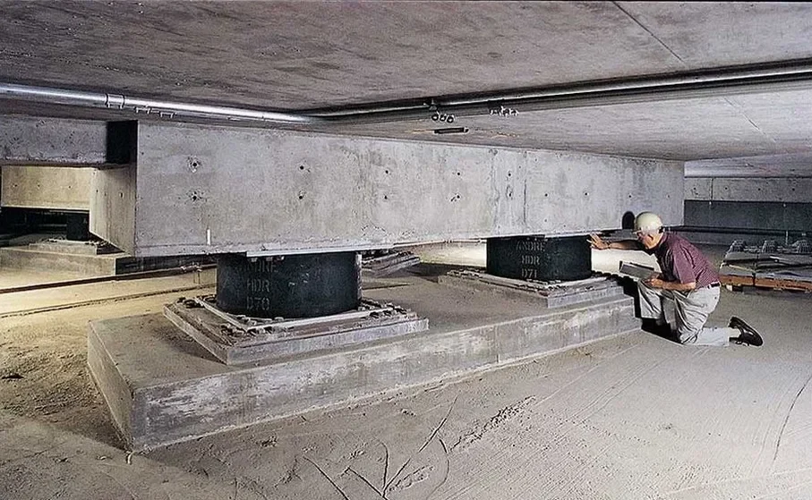
What isolator testing is required before installation in Hayward?

ASCE 7-22 Section 17.8 requires prototype testing of two isolators of each type and size at 100% and 150% of the design displacement D_M. The tests include ten fully reversed cycles at 100% D_M to verify the effective stiffness and equivalent viscous damping, plus three cycles at 150% D_M to confirm stability. Hayward Building Department also requires production tests on every isolator at 100% design displacement before shipment, per ISO 22762-1.

Location and service area

We serve projects in Hayward and surrounding areas.

View larger map